The first page considered the components and the essential preparatory work, while the previous page looked at the actual installation of the channel and a corner unit.
Finishing Off
The final part of the installation work is to fit the End Caps, to drill a hole to allow water to escape through the Outlet Unit into the underground drainage system, and to fit the Gratings.
The End Caps are shaped to match the cross-section of the channel sections and are simply slid into place as required.
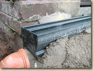
They can be retained in position with a dollop of haunching concrete or mortar, if required.
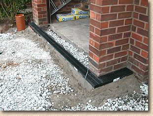
The haunching has been omitted from around the Outlet Unit that was fitted to the first section of Channel so that its position can be determined with some accuracy.
It would have been possible to drill the outlet hole and align the Outlet unit at the installation stage, but if the channel had needed to be moved one way or the other by a few millimetres, it would mean that the drilled hole would be out of alignment with the Outlet Unit and the underground drainage to which it connects. For this reason, we felt it was best to leave drilling the outlet hole until we were certain of the positioning.
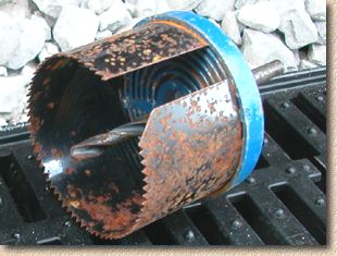
The hole through the channel is created using a Hole Saw attachment fitted to a standard drill.
Hole Saws come as a set of blades of various diameters fitted to a flange that is, in turn, mounted on a central spindle, which is usually a 10mm HSS drill bit. The various blades range from a diameter of around 25mm up to 65mm or so. The Vertical Outlet unit has a diameter of 63mm, so the appropriate blade is selected and fitted to the drill.
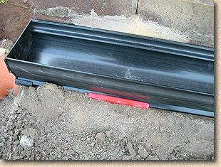
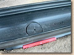
The centre of the hole needs to be established prior to cutting. Although there is some leeway in positioning the hole relative to the Vertical Outlet unit, accuracy is preferred as this makes fitting much simpler and ensures the water collected by the Aco Drive Drain is sent directly to the underground drains.
Establish the centre of the Vertical Outlet by measuring the distance from the end of the channel section to the Vertical Outlet unit on the outside of the channel section. Transfer this measurement to the internal dish of the channel, and double check. Use a pencil or sharp point to mark a transverse line indicating the centre-line of the Vertical Outlet Unit.
Once this line has been marked on the inside of the channel, the longitudinal centre line of the channel itself can be marked. The intersection of these two lines marks the centre of the required hole.
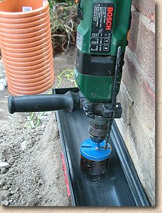
Then, it's simply a matter of fitting the Hole saw to the drill, aligning the drill point accurately and squeezing the trigger. The hole saw will slice through the Channel in just a few seconds, so keep the drill itself perfectly upright and steady.
Don't allow the Hole saw to penetrate too deeply or it risks damaging the Vertical Outlet unit beneath. As soon as the Saw burst through, release the trigger, and withdraw the drill. Hopefully, there should now be a near-perfect circle cut from the base of the channel, as can be seen in the left-hand image below.
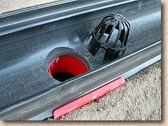
The cut circle of material can be plucked out to reveal the vertical outlet below, and a direct drop into the raising piece and P-trap. This is shown in the centre photo above.
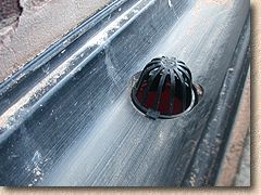
The Leaf Guard unit can now be fitted. It is pushed into the hole from above and it clips itself firmly into position. The Leaf Guard prevents larger material (and valuables) being washed into the drains and may need to be checked once every few months to ensure any litter or other obstructive material is removed.
Finally, the Gratings can be slotted into position.
As the Aco Drive Drain is designed and intended for use on residential projects, there are no locking bolts required to secure the gratings to the channels. It's also worth noting that the channels tend to grip the black plastic form of grating quite firmly and so there is little risk of the gratings coming loose accidentally.
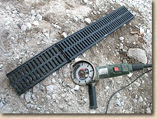
Full-length gratings are simply pushed down into place as required. Sections of channels that were cut down in size will require the gratings to be cut down to match. this is easily done with a Power Saw or Angle Grinder.
Note that it is not essential for the gratings to 'coincide' with the channels: they can bridge two units, if required. This can help de-emphasise the sectional nature of the channels and so help make the joints between consecutive channels that bit less obvious.
Once the gratings are in place, the alignment of the channels can be checked for one last time and then the whole installation can be haunched to hold it securely in place.
As this particular project will eventually be paved using tumbled concrete blocks, a mortar was used to haunch, as the finer material allows adequate anchorage to be formed without taking up too much space that will be needed to bed the pavers.
A Class II mortar (4:1) with a typical 'bricklaying' consistency was used and has held the channels in place throughout the rest of the works on this site.
Completion of Works
Once the Aco Drive Drain was successfully installed, the paving work could commence, and a few days later, the whole project was completed. The following photos illustrate the 'piecing-in' work that was done around the Aco Drive Drain and show the finished project.
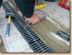
The gap between the garage floor slab and the Aco Drive Drain was paved using the tumbled concrete blocks laid on a full bed of a C20 strength semi-dry concrete. A similar "Soldier course" of tumbled blocks was laid to the drive-side of the channel.
The pavers were continued around the Corner Unit to maintain the finished "look". A parallel double-course of smaller, buff coloured blocks would be laid before completing the paving work. Also notice that the grating on the Corner Unit has now been put in the right way up!
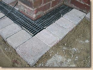
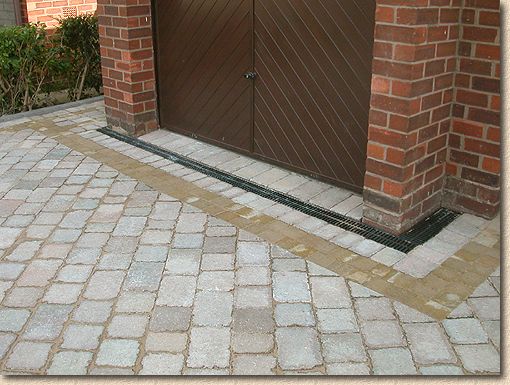
In this image of the completed work, the Aco Drive Drain looks neat and tidy, while serving a useful purpose in removing surface water from the new driveway and protecting the garage from accidental flooding. The neutral, black colouring contrasts well with both the tumbled pavers and the garage door.
Note how the course of pavers between the garage floor and the channel prevent the unsightly plain concrete floor from being seen when the garage door is shut. Look carefully at the left hand side of the garage door and you can see how this course of pavers fall out, away from the garage itself and towards the channel.
Also - what has happened to that corrugated, tan-orangey coloured Access Chamber that was on the left of the garage? It has been cut down to suit the new pavement level and covered with a Recess Tray cover , which renders it virtually invisible and further enhances the overall appearance of the completed project.
Further reading:
Further information on Aco Drive Drain and a wide range of other drainage and construction products from Aco, are available from their website .

Aco also have a PDF format document giving more information on the Aco Drive Drain that can be downloaded from this site by using the link opposite.
