Introduction:
All newly-laid drainage, including manholes, inspection chambers and the like, should be tested for water-tightness prior to backfilling, as detailed in the relevant British Standards ( BS EN 752:2008 Drain and sewer systems outside buildings) . Under site conditions, a test is applied in the presence of a Building Control Officer or Resident Engineer once a section of drainage is completed, although the contractor/pipe-layer will normally undertake a test prior to the official inspection or during actual construction to ensure the drainage will pass; there's nothing more infuriating than having your work condemned as sub-standard!
During the construction of larger sewers, an air-test is undertaken on a pipeline after every second pipe length is laid. We find this make identifying problem joints or defective pipes much simpler and less time-consuming than it would be to undertake a single test on completion of a full pipe run.
There are two basic tests; the air test and the water test . Usually, an air test is carried out to all pipework following installation, while a water test will only normally be required to verify a failed air test or to test manholes or inspection chambers . Failure during an air test is NOT sufficient reason to condemn a pipeline. If an air test indicates a leak in the system, a water test must be then undertaken to verify and quantify the problem.
Prior to any test, the pipeline should be visually inspected for any obvious signs of damage or leakage. Mortar-jointed systems should be left for at least 48 hours before instigating any test, to give the mortar a chance to set.
Tests are normally applied to a pipeline between consecutive manholes. Short branches connected to the main run are usually tested as part of the main run unless they can be easily isolated for individual testing. Manholes and IC's are tested separately using the water test.
Stoppers
Both the air test and the water test rely on the use of expanding stoppers, also known as 'bungs'. These stoppers consist of a pair of metal plates sandwiching a flexible rubber mid-section all of which is mounted along a hollow shaft. A large winged nut is fitted on top of the metal plates onto the threaded portion of the shaft and used to adjust the compression of the rubber mid-section. The top of the hollow shaft may be fitted with an end cap to form an fluid-tight seal, or with a nipple for connecting to a manometer.
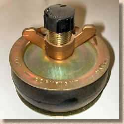
Stoppers come in a range of sizes to suit the diameter of the pipes being tested. The image shown above is a 100mm stopper which would be used for 100mm or 110mm pipes. Larger stoppers are required for 150mm or 225mm pipes. And obviously, at least two are required to seal off a section of pipework for testing. Most contractors will have half-a-dozen or more of the most popular sizes.
The inside of the pipe should be cleaned before fitting the stopper, to ensure no grit or other detritus is present that could impair the air-tight seal required for an effective test. The stopper is opened out to reduce the diameter of the rubber mid-section, before being squarely placed within the bore of the pipe and the screw mechanism gradually tightened, compressing the rubber mid-section, forcing it outwards, and pressing it against the wall of the pipe to form a tight seal.
Air Testing
The kit used to conduct an air-test is fairly basic and available from most Builders' and/or Contractors' Merchants. It consists of a number of stoppers, a hose nipple, a length of flexible hose and a manometer (a simple U-shaped pressure gauge). A small squeezy hand-pump with a control valve is often included, and this is connected to the main hose via a T-piece. The stoppers are placed in the open ends and branches of the section of pipeline to be tested and adjusted via the screw mechanism so that they expand within the bore of the pipe, effecting an air-tight seal.
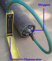
One stopper, normally at the head of the run, is fitted with the nipple that connects to the flexible hose which, in turn, is connected to the manometer, which has been part-filled with water.
Air is pumped into the pipeline, usually via a hand-pump with a control valve, until the reading on the manometer is around 125-150mm. The set-up is then left for 5-10 minutes to allow for temperature stabilisation within the pipe before the pressure is reduced to exactly 100mm on the manometer scale.
The manometer is then monitored for a period of 5 minutes; the level of water in the manometer should not fall below the 75mm mark during this period. This is deemed to be a 'pass' and the pipeline is declared satisfactory and can be backfilled. However, if the level in the manometer does fall below the 75mm mark, then the equipment should be checked and cleaned and the pipeline examined for leaks or defects. If any problems are identified, they should be rectified before re-testing. If the air test is re-applied and is failed for a second time, a water test should be administered.
The air test is considered to be more sensitive than a water test. Failure of an air test is often caused by temperature fluctuation within the pipeline caused, for example, by an uncovered pipeline being occasionally shaded by passing clouds on a sunny day. A drop in temperature of just 1°C within the pipe is sufficient to cause a drop in pressure large enough for the test to fail.
Water test
Water-testing a pipeline
A water test is not as strict as an air test, but is far more useful in identifying any leaks or bad joints that are causing the pipeline to fail the test, and is preferred to an air test by some authorities. However, an air test can be set up in a matter of seconds and dismantled without affecting the work, making it the preferred test of the pipe layer, whereas a water test can take 2 hours or more to establish, and is less convenient as an ongoing check for water-tightness of newly installed pipework. A head of water is created and the pipeline examined for tell-tales signs of leakage. Following a period of settlement and acclimatisation, the level of water in the head is monitored for a specified period and the loss of water measured and checked. It is not unknown for a pipeline that has failed an air test to pass a water test.
The size of pipe being tested will determine the test parameters. Pipes of 300mm diameter or less follow the requirements of BS8301 (1.5m head at high end; max 4m head at lower end) while larger diameter pipes (>=400mm) follow BS8005 (1.2m head at high end; max 6m head at lower end). These requirements are summarised in the table opposite. Where a pipeline would generate a head greater than that specified, it should be tested in stages, to reduce the maximum head, and minimise the risk of damage to the pipeline.
| Pipe Dia | 100-400mm | 400-750mm |
| Test to... | BS8301 | BS8005 |
| Top head | 1500mm | 1200mm |
| Max Head | 4000mm | 6000mm |
The lower end and all open branches of the pipeline to be tested are stoppered as described above. A 90° bend is added to the top end of the run and a vertical pipe of the same diameter added. This vertical pipe should be braced by lashing it to a stake or similar, as depicted.
Water is added to the pipeline (via a hose) up to the required head level in the vertical pipe and the pipeline visually inspected for leaks. The water is left to stand for at least 120 minutes, to allow for displacement of trapped air and any absorption by the pipe, before being topped up to exactly the required level.
The set-up is then monitored for a period of 30 minutes, during which the water level of the head is topped-up as required at regular intervals and the quantity of water added is recorded. After 30 minutes the total quantity of water added to the vertical pipe during the monitoring period is calculated and can be checked against the table opposite - read off the figure given for maximum acceptable loss for the diameter of pipe under consideration, and multiply that by the length of pipeline being tested. The measured quantity must be LESS than the calculated quantity for the pipeline to pass the test.
Alternatively, the maximum acceptable loss can be calculated as...
maximum permissible loss = 1 litre per hour per linear metre of pipeline, per metre of internal pipe diameter
...so, for a 75 metre run of 150mm pipe, the maximum permissible loss of water during the 30 minute test would be...
1 litre/hr × 75m × 0.15m = 11.25 litres per hour = 5.6 litres during 30 minute test period.
| Acceptable water loss | |
| Pipe Dia [mm] |
Max loss per metre in 30 mins [litres] |
| 100 | 0.05 |
| 150 | 0.08 |
| 225 | 0.11 |
| 300 | 0.15 |
| 400 | 0.20 |
| 450 | 0.23 |
| 500 | 0.25 |
| 600 | 0.30 |
| 750 | 0.38 |
| >750 | seek advice |
Water testing a Manhole or Inspection Chamber
Manholes and Inspection Chambers are tested in a manner similar to that outlined above. All inlets and the outlet of the MH/IC are stoppered and the chamber filled with water to within 300mm of the soffit. After a period of acclimatisation (60-120 minutes), the water level in the chamber is visually monitored for 30 minutes.
Acceptable water loss can be calculated on the same basis as that for pipework, although most tests look for a water loss of less than 25mm over a 10 minute period.
Smoke testing
Although testing with smoke is not an official test of water-tightness, it may be used with non-PVCu pipelines to identify leaks or defects that have not made themselves apparent in air or water tests. Some smoke canisters can damage PVCu systems, and so, if smoke is to be used within a PVCu system, it is essential a safe type is used. Check with the manufacturers before undertaking a smoke test.
Mandrel testing
This is a less common test, used on critical pipelines to verify the quality of installation. A mandrel is a ball or elliptical plug-shaped object that is passed through a pipeline to ensure that the minimum acceptable internal diameter is maintained throughout. A mandrel is typically 10mm smaller in diameter than the specified minimum diameter of the pipeline being tested, so, for a 150mm pipeline, a 135mm diameter mandrel would be used.
With flexible pipelines (PVCu) there is a degree of unavoidable deformation due to backfilling, and so the mandrel diameter is determined as being 10mm less than 95% of the pipe internal diameter. So, for a 150mm PVCu pipeline, the mandrel would be....
Making Repairs
Should a pipeline or chamber fail both an air test and a water test, then the leak/defect must be sought out and rectified before any backfilling work is undertaken. Some leaks/defects are easily identified; they may be heard to hiss as air escapes, or wetting the suspect section with soapy water may reveal tell-tale bubbling when air pressure is raised inside the pipe. Often, the fault can be identified as a single joint needing to be re-made or a faulty section of pipe to be replaced; other problems can be much more difficult to pinpoint and may need the pipeline to be dismantled one pipe length at a time and re-tested using the air test until the defective joint/pipe is located.
With MHs and ICs, the most common cause of failure is a leaking chamber section joint which can often be repaired by cutting out defective mortar/sealant and re-pointing/re-sealing as required. In some cases, it is the base of the chamber itself that is the source of the problem, often a bad seal between a pipe and the concrete surround or the base section of a pre-formed unit. Such problems may be solved with an epoxy mortar or similar, if the exact source can be identified, although in the worst cases, the only effective cure is a complete rebuild.
Once the fault(s) has been rectified, a further air and/or water test should be undertaken to ensure no further faults are present; it is not unknown for pipelines/chambers to have more than one leak!
SUDS Pages