Introduction:
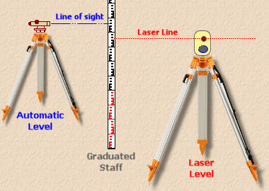
Builders and the better paving contractors will normally have an automatic (or 'dumpy') level to assist them in the setting of site levels. The more up-to-date amongst them may even have a laser level which have become cheaper and more readily available over the past few years.
Both work on the same principle - that the 'kit' is set up in such a way that it defines a horizontal plane at a known height around 360° from which accurate measurements can be taken to establish point levels.
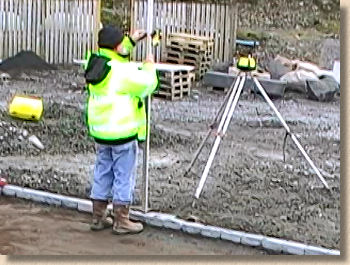
Although both automatic and laser levels could, in theory, be set-up on any stable platform (a bale of blocks, for example) it's muich better to use a tripod which can be positioned to ensure that it is simultaneously out of the way but that all points that may require levels to be established are visible.
Automatic Levels
An automatic level uses line of sight, albeit enhanced somewhat via the telescope, while a laser level emits a barely visible beam which is picked up by a detector. Both also rely on a graduated staff to measure the difference between the level plane and the point to be established.
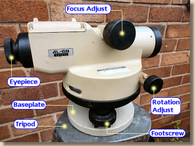
As mentioned, the 'kit' is usually mounted on a tripod. Autmatic levels have some adjustment mechanism, most commonly a set of three adjustable screw-feet that allows the 'kit' to be set to true horizontal. The better laser levels are self-levelling, so automagically adjust the mechanism internally to ensure a horizontal plane.
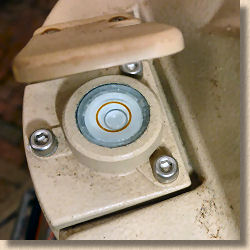
The most common system for checking horizontality on automatic levels is a circular bubble tube. The foot-screws of the unit are adjusted until the bubble is centred within the bubble tube.
Different automatic and laser levels have differing degrees of accuracy. The bubble-set kit is usually taken as accurate to with 10 minutes (one-sixth of a degree; there are 60 minutes to one degree) and should be accurate enough for most site groundworks, landscaping and paving jobs.
There are more accurate levels available for exacting work where precision is vital, but, of course, they cost a lot more.
Laser Levels
Laser levels work by generating a laser beam inside a protective housing, up to a spinning floating mirror which sends out the laser light over a reasonable distance (100-300m or so) as a truly horizontal beam.
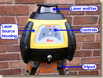
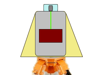
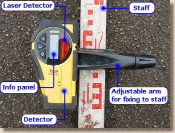
The laser beam is all-but invisible to the human eye, although special glasses can be work to make it more visible. However, this is of no consequence because rather than relying on sight, a leaser level uses a special detector which is attached to a standard graduated staff.
The detector is moved up and down the staff until the audible signal indicates it is at the precise height of the laser beam. Most detectors emit a series of beeps that get faster and faster as the detector is approaches the height of the laser beam. The sound changes to a continuous beep when at the exact level to detect the laser.
Setting-up a Station
The level unit is set-up in a position which gives a clear view of all points to be levelled, or as many as is feasible under site conditions.
Each position where the level is set-up is referred to as a 'station', and stations may be marked for future reference by means of a timber peg, steel pin, brass tag or paint mark as befits the conditions.
Marking of stations in this way allows levels and angles to be checked at a later date if a discrepancy is found.
Staffs, Benchmarks and Datums
Once the surveying station is established, the relative height of the viewing or laser plane needs to be determined. This is done by taking a measurement at a point which has a known level. This point is called a ' Benchmark ' (BM).
A Benchmark may be a known level, taken from a survey map or other official source, and given as a height in metres Above Ordnance Datum (AOD), which is usually taken as sea-level.
Levels established from this Benchmark to aid levelling elsewhere on the site are known Temporary Benchmarks (TBM).
For smaller projects, though, the absolute height AOD is of little relevance; what matters are the spot heights relative to a given point. For paving projects around the home, this given point will usually be floor level (FL) of the property, although it can be any fixed point whose height relationship with the works is known. For example, the FL of a garage could be used as the BM, as the paving has to be flush with the threshold of the garage floor and all other levels can be established from there.
The graduated staff is held vertically on the BM or TBM and a reading taken. With an automatic level, the surveyor will aim the telescope of the level at the staff and adjust the focus until the scale on the staff can be clearly seen. A measurement is then read-off from the cross-hairs of the eyepiece and recorded. With a laser level, the visible laser line will strike the receiver and a measurement can be read-off and recorded by the staff-bearer.
Most automatic levels have a magnification of around x10, which makes the staff appear much nearer and larger than it would normally seen. Even at distances of 20m or so, it's fairly simple to read off a measurement to an accuracy of ±2mm.
In this example, a reading has been taken and recorded. The next step is to transfer this level to other key points on the project and make adjustments to suit the plans.
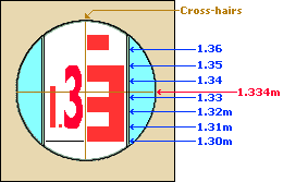
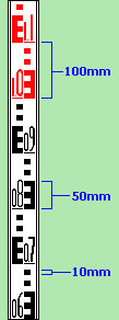
Measurement reads 1.3 from the scale, with the cross-hairs clear of the 3rd section of the 'E', so the measurement becomes 1.33, and finally the horizontal cross-hair is approximately 4/10 of the way through the white section, so the actual measurement is 1.334m.
View through automatic level Measurement reads 1.3 from the scale, with the cross-hairs clear of the 3rd section of the 'E', so the measurement becomes 1.33, and finally the horizontal cross-hair is approximately 4/10 of the way through the white section, so the actual measurement is 1.334m.
Using absolute levels
Absolute Levels means that the spot heights recorded as part of a site survey, or shown on a plan are actually the genuine height Above Ordnance Datum, which normal people refer to as "sea-level". They make a lot of sense if you are building a Nuclear Power Station. They are not quite as important if you are building a driveway where Relative Levels might be more appropriate.
Spot heights explained
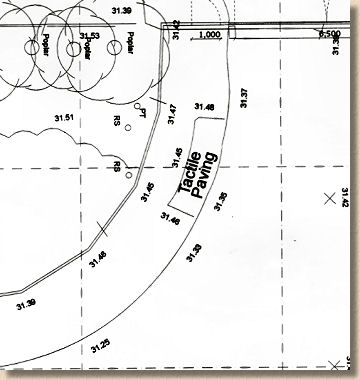
The term 'spot height' refers to the 'level' of a particular point on a site, which literally means the height at that spot. The top face of a kerbline at a particular tangent point may have a 'spot height' of 33.564 marked on a plan, and the 'spot height' of the same kerbline, 20m away where the next radius begins is marked as 33.418 so you can subtract one spot height from t'other to find the amount of fall, if any.
Spot heights are typically marked on plans and used to calculate the probable level (height) of intermediate points.
Most large-scale commercial projects will use absolute levels, so that each point anywhere on site is tallied back to one single, universal reference point: the height AOD. Throughout the project, whether it's the roofers, the plasterers or the groundworker, all designs and spot heights are taken from the same base.
There will be some point within or very close to the site that is of a known height AOD and will designated as the Master Benchmark (MBM). These points are usually publicly available known heights - you've probably seen the marks cut into fairly prominent positions on big buildings or large bridges.
For our purposes, we will assume that the level reading shown above has been taken at this MBM, and that the height AOD of this point is 112.575 metres. From this we can calculate that the line of collimation ie, the line of sight through an automatic level or projected plane of a laser level must be....

Now, if we need to establish a level at a given point (A) that is to be 112.730 m AOD, we can calculate as follows.....


....so at point A, the reading taken on the staff needs to be 1.179m. An operative will hold the staff at point A and raise or lower it as directed by the surveyor until the line of collimation intercepts the staff at 1.179 metres, whereupon the base of the staff can be marked against the pin/peg at point A. Once the pin or peg has been marked or adjusted to the correct level, it should be checked for accuracy again with the levelling equipment.
Using relative levels
On smaller projects, such as home improvements, driveways, patios and so on, the absolute level of any given point is not directly relevant; it's the relationship between various on-site spot heights that is important, and so we can use relative levels.
Basically, this means assigning a token level to some fixed point on a project, and then using that point to set out levels for the rest of the site. The token value assigned to a site benchmark ,or 'datum' as it is known, is usually 100.000 metres. This value is chosen so that any levels below the level of the datum are not negative values, which would complicate the arithmetic.
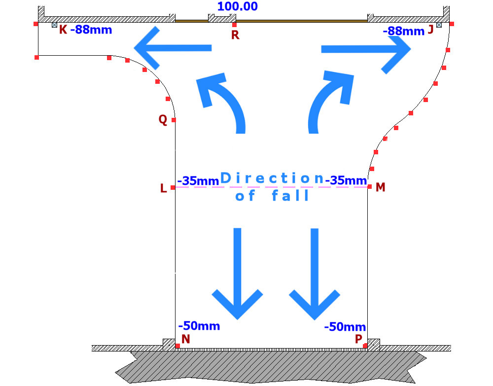
The use of relative levels for setting-out purposes is best illustrated via a worked example. We'll use the driveway project from the previous pages in this Setting Out section of the website. In the Calculating Falls sub-section, the required levels at various key points were established and these are shown on the diagram opposite.
Refer back to Calculating Falls to see how these values were determined.
The 'datum' has been positioned at point R, declared to be 100.000 metres and all other levels will be determined from that.
These plus or minus values need to be converted to values that are relative to our datum at R. They are usually referred to as 'Reduced Levels' or RL.
Point K is given as -88mm, relative to Point R, therefore....
100.000 - 0.088 = 99.912
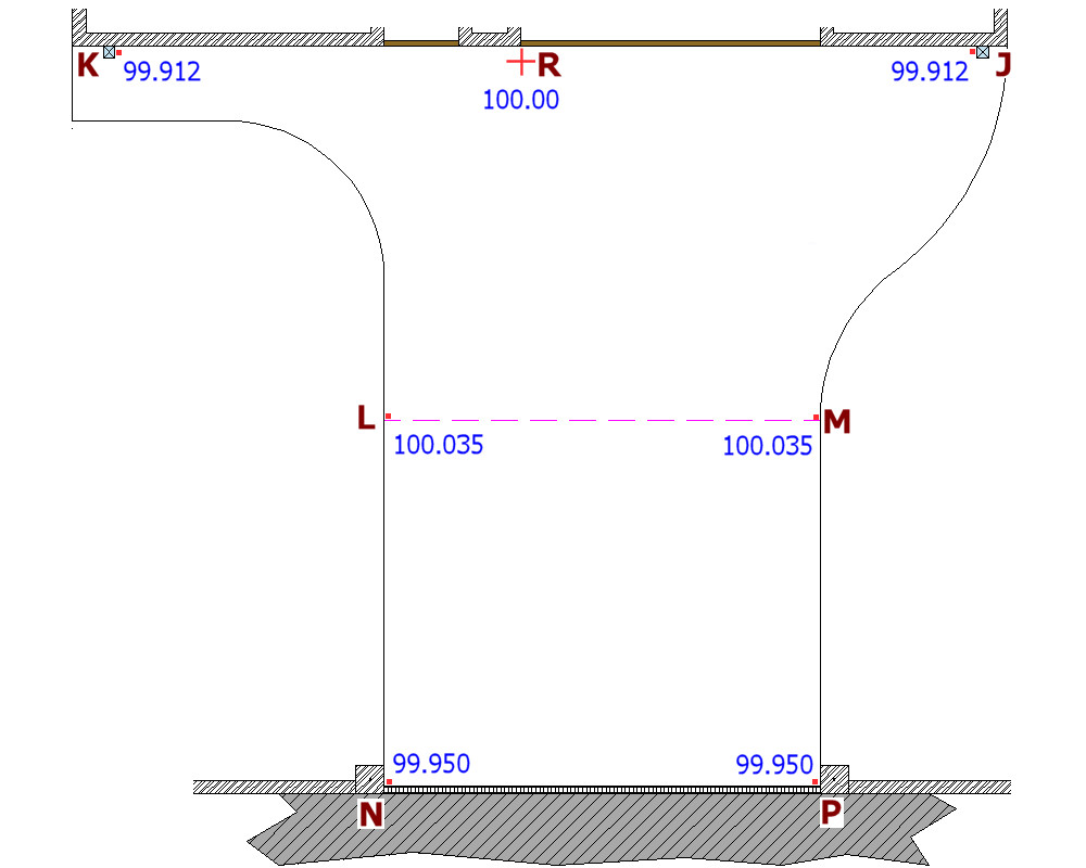
.....we can repeat this arithmetic for the other key points, and these are shown on the drawing opposite.
As explained above, we now need to establish a value for 'height of collimation', and so a reading must be taken from the staff held vertically at Point R. For ease of argument, we'll assume that the reading taken from the datum point, R is again, 1.334 metres.
This tells us that the height of instrument is, therefore, 101.334 metres.
The points J and K are to be set at 99.912 metres, so, a simple bit of maths gives us.....
101.334 ~ height of collimation
-99.912 ~ level at points J and K
=======
1.422 ~ target reading for staff
....and this process is simply repeated for the other points, working out what the staff reading needs to be at each point to establish a correct level........
Level heights for L & M
101.334 ~ height of collimation
100.035 ~ level at points L and M
=======
1.299 ~ target reading for staff
Level heights for N & P
101.334 ~ height of collimation
99.950 ~ level at points N and P
=======
1.384 ~ target reading for staff
....Now that our targets have been calculated, the procedure for level transfer outlined above can be used to establish levels at points J,K,L,M,N and P in one operation.
In most setting out jobs, there is more than one way of skinning a cat, and we could have transferred the datum level (100.000) to all the relevant points and then measured up or down from the datum mark accordingly to find the required level at each point.
Further, I've tried to avoid overly technical jargon and have only skimmed the surface of the world of surveying and setting out, so please don't regard the above as a definitive guide to the use of automatic and laser levels. It's a brief introduction and nothing more.