Introduction:
CBPP uses modified concrete blocks laid over selected free-draining aggregates to direct surface water back into the ground or send it to a suitable alternative SuDS outlet.
Permeable pavements run counter to everything we've known about modular paving since the first block paved roads were built in ancient Sumer 3,500 years ago, and Concrete Block Permeable Paving (CBPP), which is also known as Permeable Interlocking Concrete Paving (PICP) in North America, is the most contrary of all permeable paving systems. Now, instead of constructing the pavement in a way that's designed to get the water off and away from the paving as quickly as possible, we deliberately send the water into the pavement structure. Given that this turns upside down conventional pavement construction technology, it should come as no surprise to learn that the materials used to construct permeable pavements are not the standard fare: in fact, all four key elements (blocks, jointing, laying course and sub-base) are significantly different to the materials used for conventional block pavements.
Attenuation
Permeable pavements work by controlling the release of surface water to the natural environment. This is achieved by a technique known as Attenuation, which basically means slowing down or braking. Surface water is collected by the pavement and then 'held in storage' while it is slowly released to the environment in a controlled manner, minimising the risk of inundation or flooding.
In a 20th century urban environment, surface water was typically collected by gullies and channels before being dumped first into the sewer system and then into streams and rivers. Often, the sheer volume of water collected was more than could be handled by the sewers or the natural watercourses, so we experienced sewers surcharging and rivers bursting their banks. All this stems from the fact that urbanisation had created a shortcut for precipitation, drastically reducing the amount of time taken for water to reach the streams and rivers after landing on a footpath, roadway or roof.
In a completely natural environment, rain, sleet and snow would fall onto open land, soak into the ground and then gradually make its way through the soils and sub-soils towards a local stream or river, recharging natural aquifers en route. Drains, sewers, and culverts by-passed this natural process, denying the ground the chance to soak up as much of all that water as possible. Permeable paving, and other SuDS technologies, aim to redress the balance, by re-creating attenuation and allowing the ground to absorb, store, and gradually release collected water in a more controlled manner, much like a great big huge soakaway.
Attenuation, then, involves a wide range of strategies that slow down the return of water to the streams and rivers.
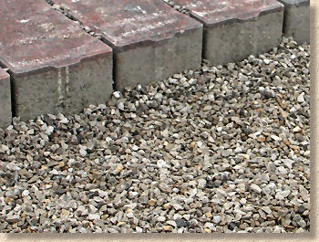
For permeable block paving (regardless of whether they are concrete, clay or stone pavers) the key to creating all this invaluable attenuation is achieved by using a specially adapted sub-base . This sub-base material, unlike the stuff used for conventional paving (DTp1, DTp2, 803, 804), contains almost NO FINES which results in a high proportion of void spaces within the material. These void spaces are what gives the sub-base its ability to store all that water collected by the pavement surface.
Think of the sub-base acting as a huge sponge, soaking up and storing all the incoming surface water when it's raining. Some of that incoming water will go straight to ground (more or less), as the 'sponge' always allows water to escape. However, the rate of water coming in to the sub-base sponge will often exceed the rate at which it can escape, so the sponge acts as a reservoir, gradually releasing stored water to the environment at a more manageable rate over an extended period of time, thereby reducing the impact of a sudden surge of water and the likelihood of flood events.
The sub-base material is a specially selected hard material (primary or secondary aggregate) of an angular nature that generates a high degree of interlock and thereby gives the compacted material adequate stability to enable it to carry the weight of the overlying layers plus any traffic. There are various sub-base requirements determined by anticipated traffic loads and the strength of the sub-grade (CBR). Heavily trafficked areas and/or those constructed over poor ground may incorporate improvement layers of "hydraulically bound material" (techno-babble for no-fines concrete) and/or porous dense bitumen macadam (DBM) - see below . Technical and hydraulic design is beyond the remit of this page, and so it is not covered any further here, but will be examined in detail on future pages.
Three basic systems
The sub-base layer is intended to act as a reservoir, to provide storage for collected surface water and to release it to the natural environment at a controlled rate. The simplest model involves water accumulating within the sub-base from where it slowly seeps into the ground beneath. This is shown below....
Note: the use of an intermediate Geo-Grid stabiliser is a patented design of Forterra Formpave
This Total Infiltration arrangement has been dubbed "System A" in " The SUDS Manual " published by CIRIA . In effect ALL of the water is required to infiltrate the ground eventually.
Essentially, the sub-base is designed to have a storage capacity greater than that which would be required by a once-in-so-many years storm event. Water percolates into the sub-base from the surface where it is stored and gradually released. The quantity of water retained within the sub-base will vary: more when it's raining, less when it's been dry for a period.
However, there are situations when simply relying on the storage capacity of the sub-base and the rate of percolation of the ground would not be adequate. It may be that the ground is clayey and slow-draining, or that the pavement is subject to exceptional events that involve very large quantities of water being sent to the sub-base. Obviously, in such situations, having some form of 'overflow' facility would be beneficial, which brings us to "System B"...
...which is a Partial Infiltration system. The position of the 'overflow pipe' can be established to suit local conditions. The higher up the sub-base it is placed, the greater will be the quantity of water stored before overflow conditions occur. There are designs that place the overflow pipe at the bottom of the sub-base layer: these designs often involve a relatively free-draining sub-grade and the overflow pipe is provided to remove any excess water that does not escape to the sub-grade fairly quickly. Bear in mind that these overflow pipes would be installed at some distance from their neighbouring pipes, thereby giving the collected water maximum opportunity to go to ground before being removed by pipe to a secondary suds installation (such as a soakaway or swale) or allowed to enter a sewer system or watercourse.
The third and final system, with the too-damned-clever-by-half title of "System C" is a No Infiltration system. Yes: that's right, no infiltration. None of the collected water is allowed to escape to the ground.
You may wonder what the point of such a system might be. Well, there are instances when it is not desirable for the collected water to go to ground. The two simplest examples are when there is a risk of pollution and when rainwater harvesting is required.
Where permeable pavements are installed to polluted or pollution-generating sites, allowing contaminated water to escape to ground would not be a good idea. Instead, the water can be collected, stored and diverted to a suitable treatment facility before being cleaned-up before being allowed to return to the natural environment, usually via a SuDS installation. A good example of such an installation would be a Fire Service training area, where foam and other chemicals are regularly washed over a large open space. The run-off from such a site could be collected by a permeable pavement and stored prior to cleaning.
In drier parts of the world, rain-water represents a valuable commodity, and so it makes sense to retain collected water for use as ' grey water ' rather than allow it to escape to ground.
In these No Infiltration systems, a collector pipe penetrates the tanked construction to allow water to be drawn off as required, for re-use (as grey water) or for treatment. In rainwater harvesting systems, the pipe may also act as an overflow pipe, removing excess water to be transferred to another suds installation, to a storage tank or, as a last resort, to be sent to the local sewer or watercourse.
Typical structure
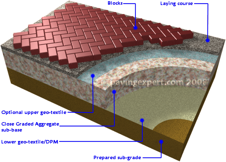
Partly because concrete/clay block permeable pavements are a relatively new development, there is still quite some difference in what might be considered a typical structure. The section above looked at three systems, but regardless of the differing applications to which these systems might be applied, the structure shown is essentially constant: blocks - laying course - sub-base -sub-grade. However, in real life, that structure, and particularly the sub-base, may be significantly different to that shown.
Blocks
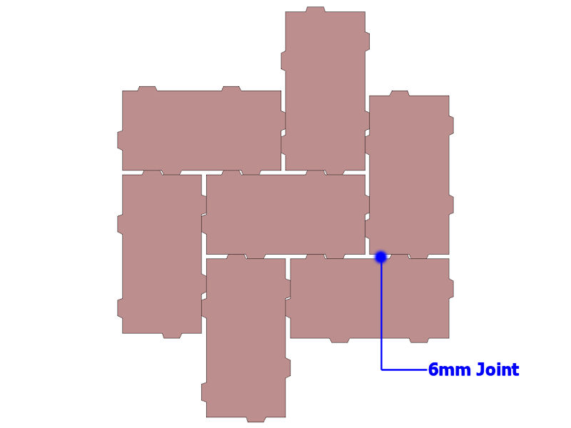
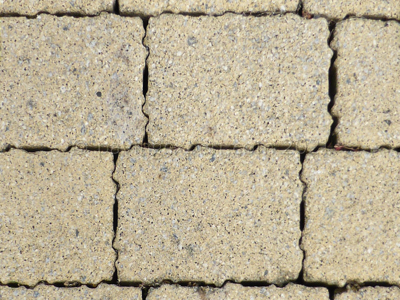
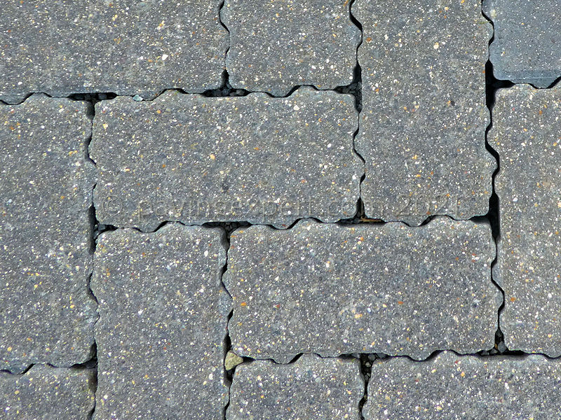
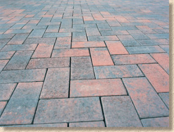
The blocks are fairly constant. There are all sorts of formats, but the industry has largely settled on a format that features a block with spacer nibs that help create wider-than-normal joints for the water to pass through.
On some blocks, the spacer nibs will be extra-large and arranged in an offset pattern to create a joint of approximately 6mm width. Other manufacturers elect to rely on 'standard' 3mm spacer nibs but have them arranged on the blocks so that they will lie nib-to-nib and thus create the 6mm joint.
And just to complicate things, there are also blocks which combine the two: nibs that are offset alongside complementary nibs.
Some of the different formats are shown below.
Laying Course
There is some variation regarding the laying course, some due to regional factors particularly availability of suitable aggregates, and some due to manufacturer preferences, with some claiming such-and-such a material being better suited to their particular block format (and usually omitting to mention that they own the only quarry that can supply the aforesaid super laying course material).
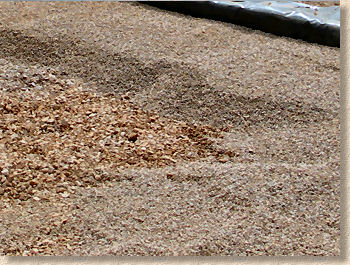
The latest edition of BS7533:3 (2009 edition with A1) gives a grading guide for a suitable laying course material. This is shown opposite.
Notice how, in the simplest of terms, it is essentially a 6-2mm clean hard grit. No fines, as the presence of fine material would simply clog and impede the free passage of water through to the sub-base beneath, and is typically angular or sub-angular in shape to generate a good level of interlock.
Compared to the material used as a laying course for conventional paving, this material is much coarser with far less fine material. A comparison of the grading envelopes shows that the permeable laying course material, on the right, has a higher proportion of the larger, coarser particles compared to the conventional material on the left.
Not only is the laying course material free of fines, which dramatically affects its handling and compactability, there's more of it. The recommended thickness of a laying course in a conventional pavement is given as 25-40mm, but for permeable pavements, the recommendation is an even 50mm. This increased thickness is used to accommodate the rather limited compaction that takes place with this type of aggregate - apparently, consolidating 50mm thickness gives more reliably consistent compaction than is the case with 40mm or even less.
Sub-base
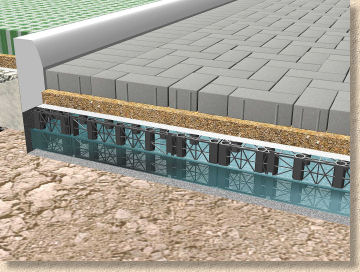
Sub-base replacement systems
It is this layer that represents the biggest change to conventional block paving. The material is very different to the DTp1 or 804 that is normally used for sub-base construction, and there is also the option to use a "sub-base replacement systems" that can be used to replace some or all of the sub-base. These invariably involve the use of lattice-like cells that can be linked together to create the length, width and depth required. In principal, they are identical to the attenuation cells or so-called "storm crates" discussed in the drainage section of this site, with the exception that they tend to be shallower (150-250mm) giving greater control over sub-base depth.
Theses alternative structures offer a number of benefits:
- increased storage capacity
- reduced excavation depth
- increased stability on poor ground
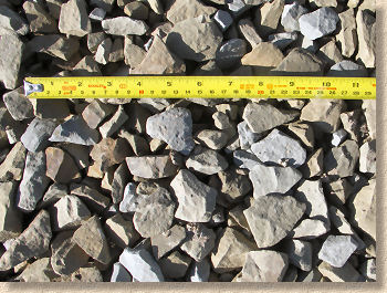
Coarse Graded Aggregate
See also DTp3 on the sub-bases page
Increasingly referred to as CGA, this is the name that's been assigned to the specially selected sub-base aggregates to be used with permeable pavements. There is some variation in just what exactly is used, due to regional differences in availability and the preferences of the various manufacturers.
The 'official' grading distribution table is shown opposite but it must be borne in mind that some suppliers will recommend, say, a 4-40mm material while others will suggest a 5-20mm product. And just to complicate matters, there are designs that involve a lower layer of larger material (as large as 20-63mm) beneath and upper layer of smaller stone (5-20mm).
For pavements that will be subjected to heavy traffic loads, there is the possibility of incorporating a permeable layer of bound material within the sub-base. This may be "hydraulically bound" (concrete to us mere mortals) or dense bitumen macadam (DBM). The concrete option is often referred to as a "No Fines Concrete" and is based on the same grading distribution as shown in the table above and will have a relatively low cement content, typically 3-10%. When DBM is used, it will need to be cored (or punched) at regular intervals to provide 'escape routes' for any trapped water, with the resulting holes filled with the coarse graded aggregate described above.
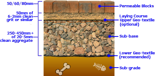
However, for the typical residential installation including driveways, a single-layer sub-base of 250-350mm of the CGA will be adequate; 250mm for patios and light driveways, 350mm for driveways carrying vans or heavy 4x4s. It's worth noting the additional construction depth involved in a permeable pavement compared to conventional. Whereas a typical conventional residential driveway would feature a total build-up of 240mm (50 block + 40 bed + 150 sub-base), a permeable pavement would have at least 360mm (60 block + 50 bed + 250 sub-base), and increase of 50%. Consequently, CBPP driveways and patios will require additional excavation and cart away, which is relatively expensive, as well as additional sub-base material.
Geo-textiles
There has been an enormous amount of debate regarding the use of geo-textiles within permeable pavements, and the argument is still not resolved. To summarise: while most parties accept that a lower geo-textile (or DPM in the case of zero infiltration systems) is essential, the main debate revolves around the perceived need for a second geo-textile layer between laying course and sub-base. One side argues that the geo-textile is necessary to prevent 'trickle down' of the finer laying course material into the open-textured sub-base and the consequent settlement that would occur, while the other side argues that careful selection of laying course and sub-base material will minimise, if not eliminate, the incidence of 'trickle down'. There is also some discussion regarding the potential for an upper geo-textile to act as a 'slip membrane', allowing the blocks and laying course to 'slide' and shift position independently of the sub-base.
There is an equation used to determine the 'compatibility' of laying course and sub-base that involves quantifying the proportion of particle sizes in both aggregates and ensuring that the difference between the two falls within certain parameters. This is not a calculation that could be done by a typical contractor and is a task for an engineer with access to laboratory facilities. While this may be practical for commercial schemes, it is unlikely to take place on residential projects, and so it is likely that most residential installations will err on the side of caution and incorporate the upper geo-textile rather than risk settlement and disgruntled customers.
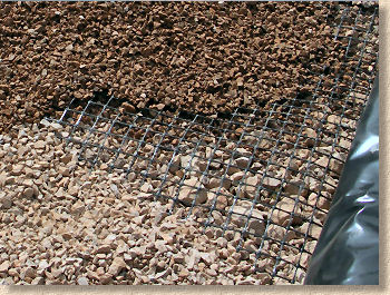
As if that wasn't enough, there is also some disagreement over the presence of an intermediary geo-grid within the sub-base. Some parties believe that a geo-grid will help stabilise and stiffen a sub-base, particularly when more than 225mm of material is used, while others argue that there is adequate interlock between individual particles within the sub-base material and that a geo-grid is an unnecessary cost imposition.
All of these arguments stem from the fact that CBPP is a relatively new technology and most of the arguments are based on theory rather than empirical evidence. As the number of installations grows, and as more and more CBPPs attain a service life into double figures, it's quite likely that these arguments will be resolved and in a decade or so we will have a 'standardised' installation recommendation.
It should be noted that the choice of geo-textile is critically important. They MUST be construction grade geo-textiles and not so-called weed membranes or landscape fabrics which simply do not have the shear strength or puncture resistance to perform as required. There are a wide range of suitable geo-textiles from a selection of accredited manufacturers and suppliers, many of whom are listed in the suppliers section of this website.
Jointing
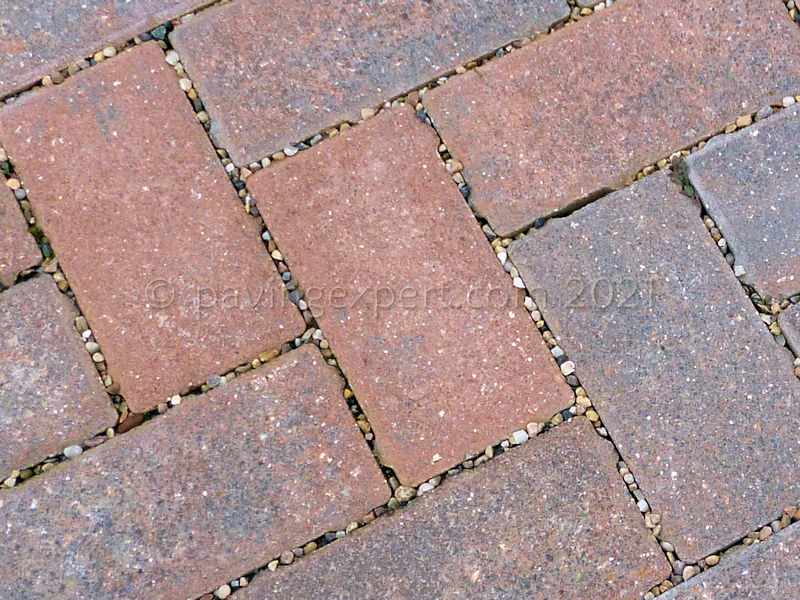
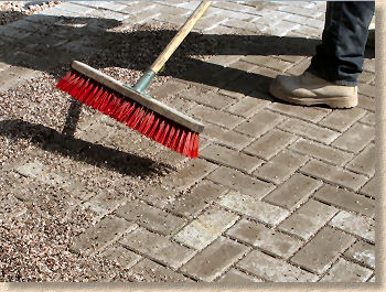
As with conventional paving, the jointing used between the individual blocks is critical to the stability and strength of the pavement as a whole. However, it would be impractical to use the kiln-dried sand that is used with conventional paving as this would rapidly be lost to the open-textured laying course. Consequently, a coarse, no-fines aggregate similar (if not identical) to the laying course material is used as a jointing medium.
In fact, there is so much variation in what is used as a jointing material that the relevant British Standard ducks the question and refers readers to the manufacturers for advice on what might be most suitable for their particular paving system. Generally speaking, a 4-1mm clean hard crushed stone will be used, and, as with conventional pavements, it is simply a matter of sweeping the jointing material into the empty joints and settling in with the aid of a vibrating plate compactor.
Other permeable paving pages...